Siemens S7-1200 “Servo Control” with Mitsubishi MR-J4-A: A Comprehensive Tutorial
Written by FAIZAL AFZAL
Introduction
In modern industrial automation, the Siemens S7-1200 PLC and the Mitsubishi MR-J4-A Servo Motor are two of the most widely used devices globally. Their combination provides a powerful solution for precise motion control in various factory settings. This tutorial aims to guide you through the process of using the Siemens S7-1200 PLC to control the Mitsubishi MR-J4-A Servo Motor. The steps outlined below will ensure that even those new to PLC programming and servo control can achieve success.
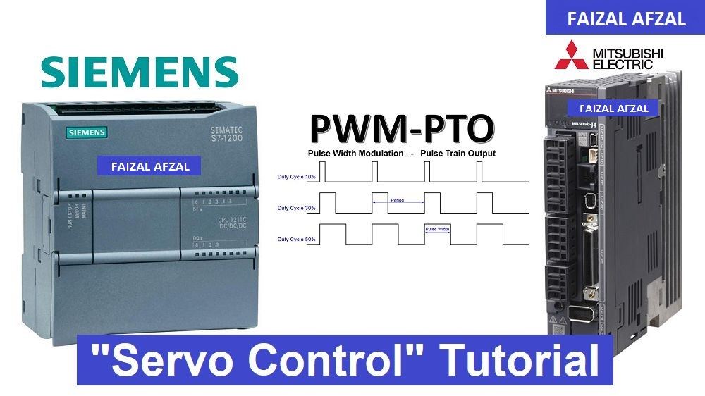
Step 1: Wiring Diagram for Siemens S7-1200 & Mitsubishi MR-J4-A
1.1 Overview of the Wiring
The first step in controlling the Mitsubishi MR-J4-A Servo Motor with the Siemens S7-1200 PLC is setting up the correct wiring. Proper wiring ensures that the PLC can send the necessary commands to the servo motor, enabling it to execute precise movements.
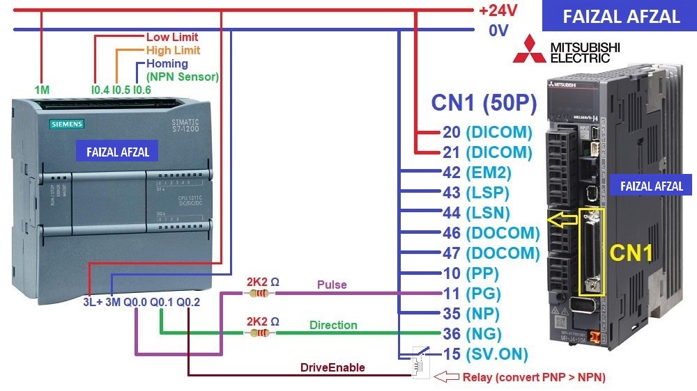
The wiring diagram between the Siemens S7-1200 PLC and the Mitsubishi MR-J4-A Servo Motor. The image should clearly depict connections for power, I/O signals, and communication lines.
1.2 Detailed Wiring Connections
- Power Supply: Ensure that both the S7-1200 PLC and the MR-J4-A Servo Motor are connected to their respective power supplies. Double-check that the voltage levels meet the requirements specified in their respective manuals.
- I/O Connections: Connect the PLC’s output terminals to the servo motor’s input terminals, specifically for pulse output and direction control. The proper wiring of these signals is crucial for accurate servo operation.
- Limit Switches and Sensors: Connect the limit switches and homing sensor to the PLC’s input terminals. These sensors provide critical feedback to the PLC, ensuring safe and accurate movement of the servo motor.
Step 2: Configuring the Siemens S7-1200 I/O Addressing
2.1 Overview of I/O Addressing
In this step, we will configure the I/O addresses on the Siemens S7-1200 PLC to match the connections made in the wiring diagram. This allows the PLC to correctly interpret signals from the sensors and control the servo motor.
2.2 I/O Address Table
- Input Addresses:
- I0.4: Low Limit Switch Sensor
- I0.5: High Limit Switch Sensor
- I0.6: Homing Sensor
- Output Addresses:
- Q0.0: Pulse Output
- Q0.1: Direction Output
- Q0.2: Servo ON/OFF Control
By correctly setting these addresses, you ensure that the PLC can properly manage the servo motor’s movements based on sensor inputs and control commands.
Step 3: Mitsubishi MR-J4-A Driver Configuration
3.1 Overview of Driver Configuration
The Mitsubishi MR-J4-A Servo Motor driver must be configured correctly to respond to commands from the Siemens S7-1200 PLC. This step involves setting key parameters that govern how the servo motor interprets input pulses and controls its movement.
3.2 Key Parameters to Configure
The following parameters must be configured using the MR-Configurator2 software (available for download):
- PA1: Servo Control Mode Selection
- Value: Set to
1000. - Purpose: This parameter selects the position control mode, enabling precise positioning based on pulse commands from the PLC.
- Value: Set to
- PA5: Pulse Command Input Setting
- Value: Set to
1000 Pulses / Revolution. - Purpose: This setting determines the number of pulses required for one full revolution of the servo motor, which is critical for accurate movement control.
- Value: Set to
- PA6/PA7: CMX/CDV (Input Pulse Gain Ratio)
- Default Value:
1/1. - Purpose: Adjusts the pulse/revolution ratio to match the PLC’s pulse output. The default setting corresponds to
131072 pulses/rev.
- Default Value:
- PA13: PLSS (Selection of Control Pulse Types)
- Default Value:
0100. - Purpose: Configures the type of pulse input that the servo motor will accept. This must be set correctly to ensure compatibility with the PLC’s pulse output method.
- Default Value:
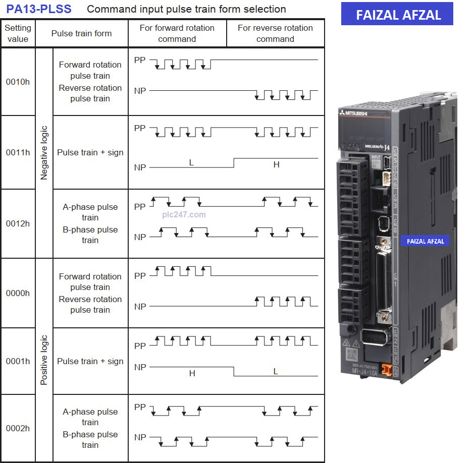
Table here showing the different Control Pulse Types
Step 4: Configuring Siemens S7-1200 Pulse Train Output (PTO)
4.1 Overview of PTO Configuration
The Siemens S7-1200 PLC uses the Pulse Train Output (PTO) function to control the servo motor’s movements. Configuring the PTO involves setting basic, extended, dynamic, and homing parameters to match the specific requirements of your application.
4.2 Basic Parameters Configuration
- Axis Configuration: Set up Axis1 for the S7-1200, ensuring that the basic parameters such as pulse frequency, duty cycle, and direction control are correctly configured.
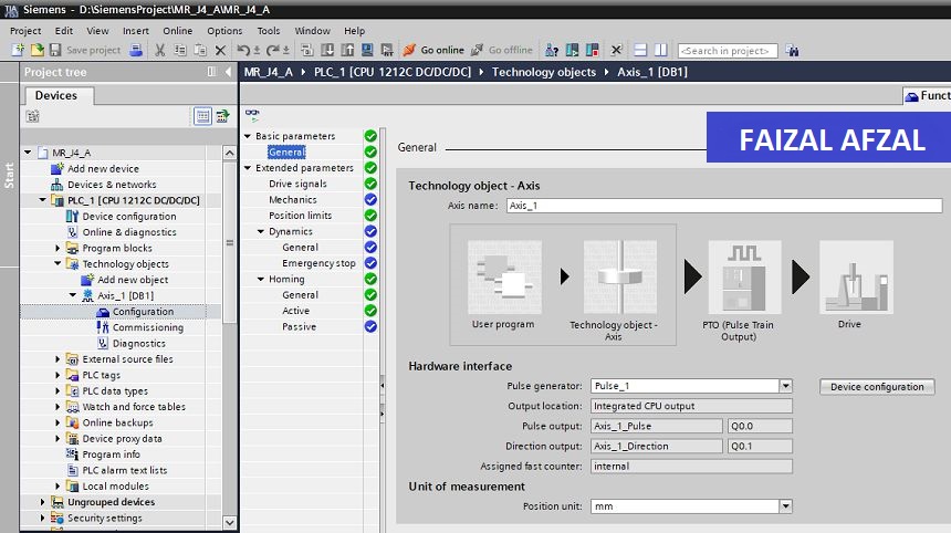
The basic parameters configuration screen in the Siemens TIA Portal software.
4.3 Extended Parameters Configuration
- Acceleration/Deceleration Settings: Configure the extended parameters to include acceleration and deceleration rates, which determine how quickly the servo motor reaches its target speed and how smoothly it stops.
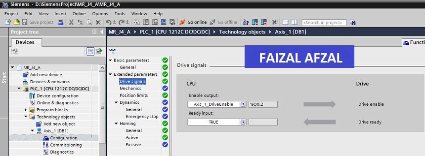
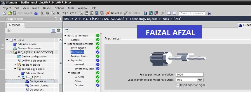
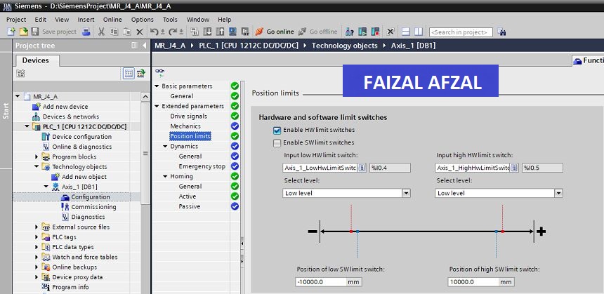
The extended parameters configuration screen.
4.4 Dynamic Parameters Configuration
- Speed and Torque Limits: Adjust the dynamic parameters to set speed and torque limits, ensuring that the servo motor operates within safe limits without overloading or overheating.
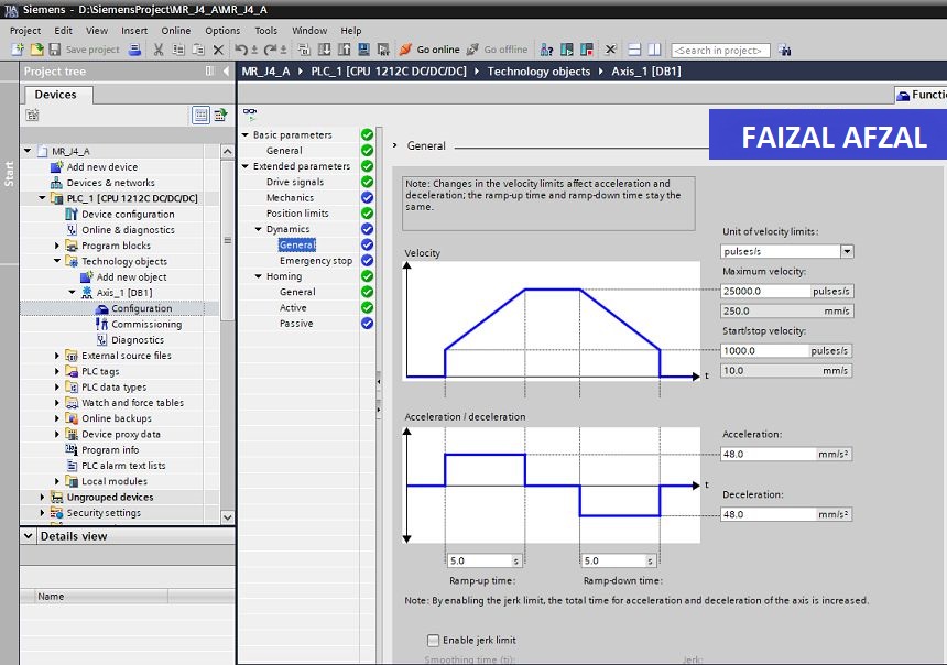
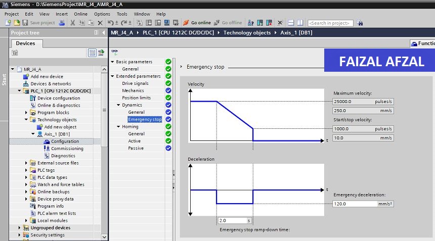
The dynamic parameters configuration screen.
4.5 Homing Parameters Configuration
- Homing Method: Set up the homing procedure to ensure the servo motor returns to its origin (home) position accurately. This is critical for operations that require the motor to start from a known reference point.
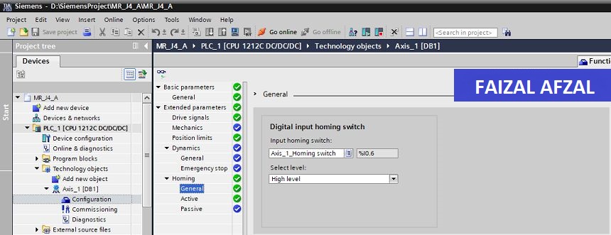
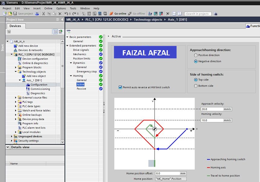
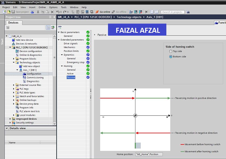
The homing parameters configuration screen.
Step 5: Siemens S7-1200 Servo Control Programming
5.1 Overview of PLC Programming
Programming the Siemens S7-1200 PLC to control the Mitsubishi MR-J4-A Servo Motor involves creating a program that manages pulse output, direction control, and servo ON/OFF states. This program must also handle inputs from sensors and execute homing sequences.
5.2 Basic Control Program
Here is a simple example of a control program that can be used to manage the servo motor:
- Servo ON/OFF Control: The program should include logic to turn the servo motor on and off based on specific conditions, such as sensor inputs or operator commands.
- Pulse and Direction Control: Implement the logic to output pulses and control the direction of the servo motor. This ensures that the motor moves to the correct position as required by the application.
- Homing Sequence: The program should include a homing sequence that moves the servo motor to its home position at the start of the operation.
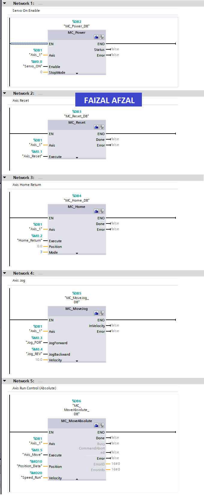
The control FB’s used in the Siemens TIA Portal software to control the servo motor.
5.3 Advanced Features (Optional)
For more advanced applications, consider adding features such as:
- Speed Control: Adjust the motor’s speed dynamically based on process conditions.
- Error Handling: Implement error detection and recovery mechanisms to handle faults in the servo system, ensuring continuous and safe operation.
Conclusion
This tutorial provided a detailed guide on how to control a Mitsubishi MR-J4-A Servo Motor using a Siemens S7-1200 PLC. By following these steps, you can achieve precise motion control in your industrial automation projects, ensuring reliable and efficient operation.
For further learning, consider exploring advanced PLC programming techniques and servo motor control strategies to enhance the capabilities of your automation system.