Mitsubishi FX3U “Servo Control” Tutorial
Written by FAIZAL AFZAL
Introduction
The Mitsubishi FX3U PLC (Programmable Logic Controller) is renowned globally for its affordability, ease of programming, and versatility. This tutorial is designed to provide a comprehensive guide on using the Mitsubishi FX3U to generate pulses to control the MR-J4-A Servo Motor, one of the most widely recognized servo motors in industrial applications.
In this guide, we will cover everything from wiring diagrams to programming instructions, ensuring you have a thorough understanding of how to effectively control the servo motor with the FX3U PLC.
Wiring Diagram: FX3U & MR-J4-A Servo Motor
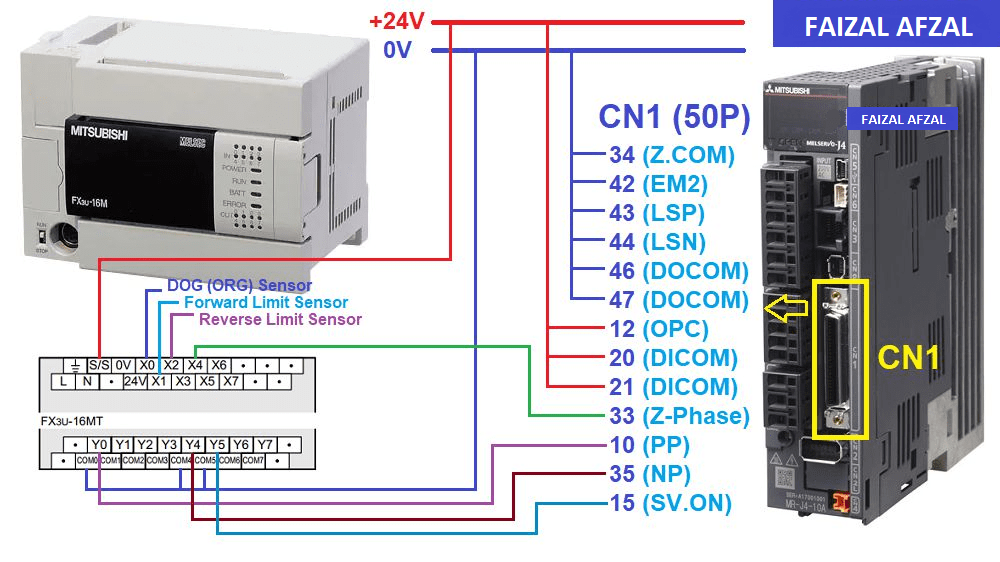 Detailed wiring diagram of the FX3U PLC connected to the MR-J4-A Servo Motor. This diagram clearly show all connections, including power supply, input/output terminals, and communication interfaces.
I/O (Input/Output) Map Table
To manage the integration between the FX3U PLC and the MR-J4-A Servo Motor, it is essential to correctly map the inputs and outputs. Below is the I/O map that you will need:
Input Signals
- X0: DOG (Origin) Sensor – Normally Open (NO) Contact
- X1: Forward Limit Sensor – Normally Closed (NC) Contact
- X2: Reverse Limit Sensor – Normally Closed (NC) Contact
- X4: Z-Phase Signal – Input from Servo Motor
Output Signals
- Y0: Pulse Output – Controls the pulse signals sent to the servo driver.
- Y4: Direction Output – Determines the rotation direction of the servo motor.
- Y5: Servo ON Output – Engages the servo motor.
Mitsubishi MR-J4-A Driver Settings
To ensure proper operation, the MR-J4-A Servo Driver must be correctly configured. Below are the essential parameters and settings that need to be adjusted:
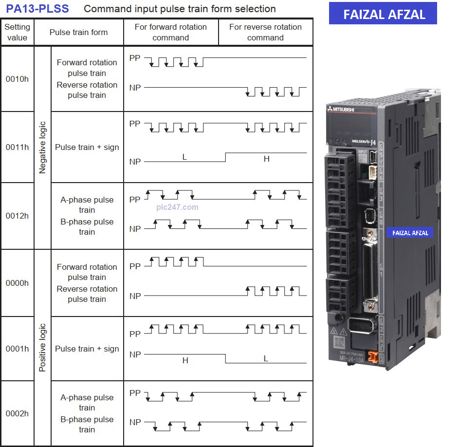
Table showing the key parameters of the MR-J4-A driver, such as pulse mode, input/output settings, and any other critical configurations.
Key Configuration Steps:
- Speed Control: Ensure the servo driver is configured to receive speed commands via pulses.
- Pulse Input Mode: Set this parameter to accept pulses from the FX3U PLC.
- Direction Control: Configure the driver to interpret the direction command from the PLC.
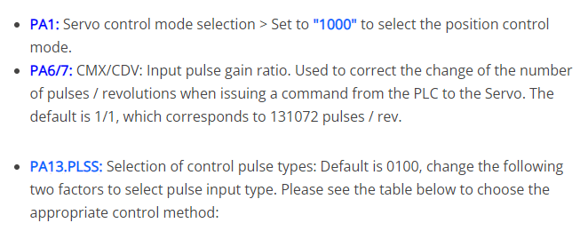 By setting up these parameters correctly, the servo motor will respond accurately to the commands issued by the FX3U PLC, ensuring smooth and precise motion control.
FX3U Instruction Commands
To control the servo motor, the FX3U PLC uses specific commands that must be programmed into the PLC. Below are the key instructions required for controlling the MR-J4-A Servo Motor.
1. Zero Return (Origin Return) Command
This command is used to return the servo motor to its origin (home) position.
- S1: ORG Sensor – Input device number for the near-point signal (DOG) sensor.
- S2: Z-Phase Signal Input – Input from the servo motor’s Z-Phase output.
- D1: Pulse Output Number – Designates the output channel for pulses.
- D2: Rotation Direction Signal Output – Specifies the output channel for the direction command.
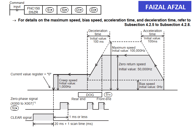
Example image of the origin return setup
2. Absolute Pulse Output Command
This command allows the FX3U PLC to send a specific number of pulses to the servo motor to move it to a designated position.
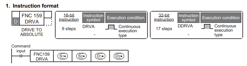
- S1: Number of Output Pulses – Specifies the absolute address or position.
- S2: Output Pulse Frequency – Defines the speed at which the pulses are sent (speed control).
- D1: Pulse Output Number – Specifies the pulse output channel.
- D2: Rotation Direction Signal Output – Controls the direction of movement.
PLC Programming for Servo Motor Control
1. Servo ON & Origin Return Command
The first step in programming the FX3U for servo control involves turning on the servo and sending it to the origin position.
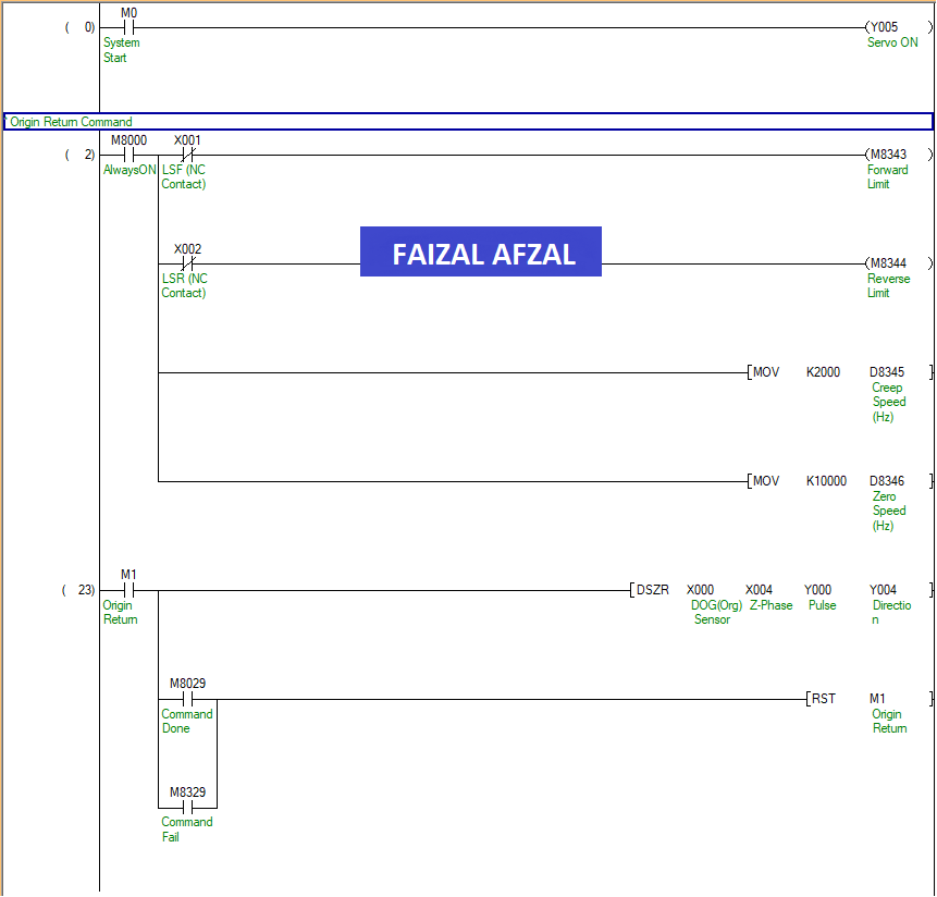
Ladder logic showing the Servo ON and Origin Return commands
2. Servo Control Command (Three Independent Position Control)
In this step, we will program the FX3U to control the servo motor to move to three independent positions. This simple and efficient approach provides flexibility in controlling the motor’s position based on the application’s requirements.
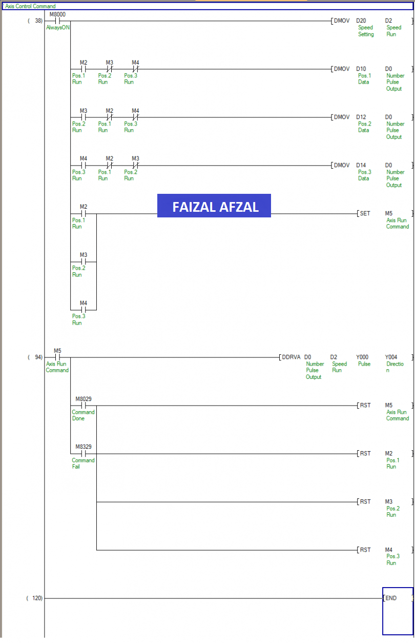
Image of the corresponding ladder logic for controlling three independent positions
Detailed Explanation:
- Position 1 Control (M2): Engage the servo motor to move to the first predefined position.
- Position 2 Control (M3): Command the servo motor to the second position with specified pulses and speed.
- Position 3 Control (M4): Move the servo motor to the third position, completing the sequence.
Each command utilizes the DMOV instruction to transfer data to the pulse output and speed registers, ensuring precise control of the servo motor.
Conclusion
This tutorial has walked you through the process of controlling a Mitsubishi MR-J4-A Servo Motor using the FX3U PLC. By following the wiring diagrams, correctly mapping the I/O, setting up the driver parameters, and programming the necessary PLC instructions, you can achieve precise and efficient control of the servo motor.
If you have any further questions or need additional support, please refer to the Mitsubishi manuals or contact a Mitsubishi representative.