Comprehensive Guide to Setting Up the Mitsubishi MR-J4-A Servo Drive
Introduction
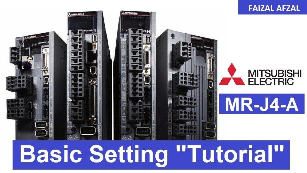
The Mitsubishi MR-J4-A servo drive is an integral component in industrial automation, widely utilized across various applications due to its precision and versatility. It is compatible with several Mitsubishi servo series, including MR-J2S, MR-J3, MR-J4, and MR-JE. This tutorial will guide you through the complete setup and configuration of the MR-J4-A servo drive, leveraging the MR-Configurator 2 software to streamline the process. This detailed guide will help both new and experienced users efficiently install and configure the MR-J4-A servo drive.
1. Software Installation
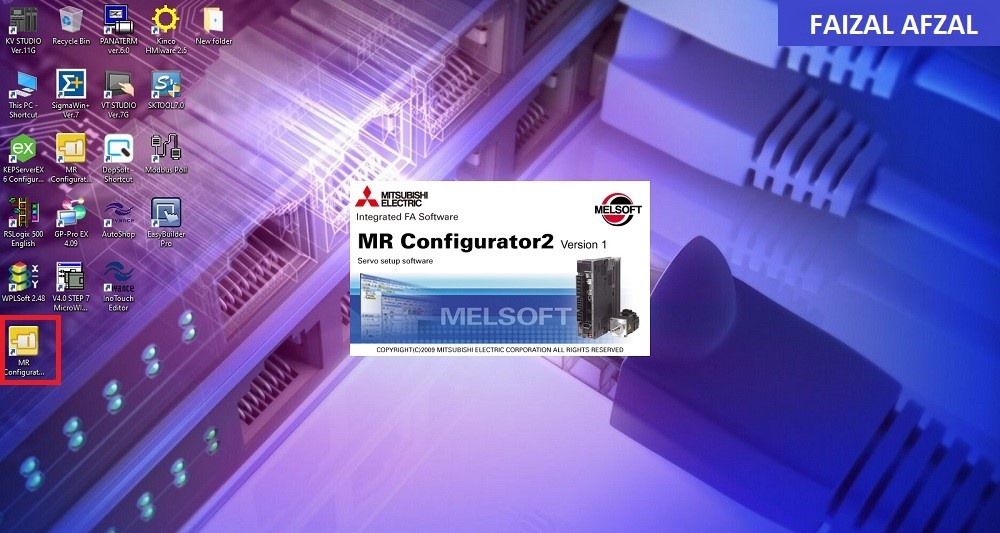
Step 1: Download and Install MR-Configurator 2
- Action: Download the MR-Configurator 2 software from Mitsubishi Electric’s official website or an authorized distributor.
- Purpose: MR-Configurator 2 is essential for configuring and monitoring parameters of the MR-J4-A servo drive. It simplifies the process of setting up the servo drive by providing a user-friendly interface.
- Link: Download MR-Configurator 2 Software
Installation Instructions:
- Download the software from the provided link.
- Follow the installation wizard to complete the setup on your computer.
- Ensure the software is up-to-date for compatibility with the MR-J4-A servo drive.
2. Connecting the Servo Drive
Step 2: Connect to the MR-J4-A
- Required Equipment: Mini USB cable.
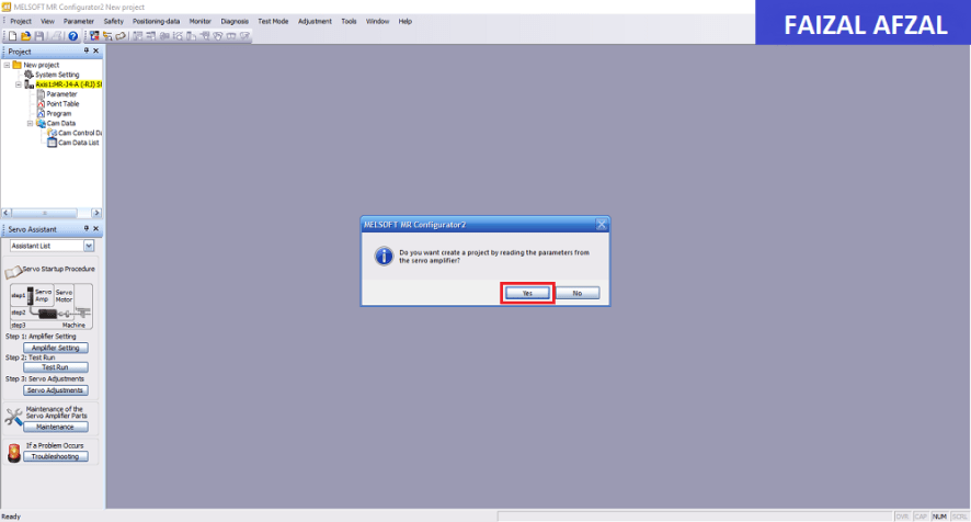
- Action: Use the mini USB cable to connect the MR-J4-A servo drive to your computer.
- Connection Notes:
- Direct Connection: Allows for real-time parameter reading and adjustments.
- Offline Configuration: Parameters can also be set without a direct connection, using predefined values.
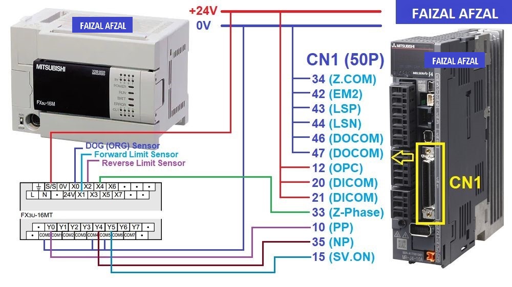
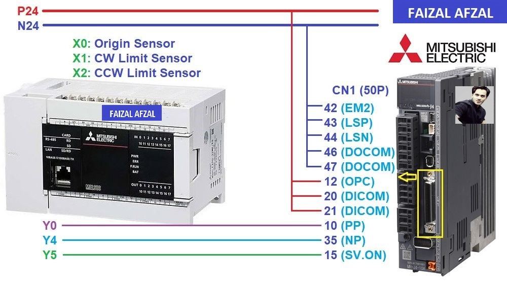
Note: Connection Diagram Ensure proper connection by referring to the provided connection diagrams specific to your PLC model.
3. Configuring Parameters
Step 3: Access Parameter Settings
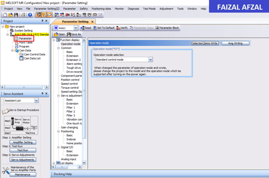
- Action: Open MR-Configurator 2 and navigate to the “Parameter” settings.
- Purpose: This section allows you to adjust various parameters crucial for optimal performance of the MR-J4-A servo drive.
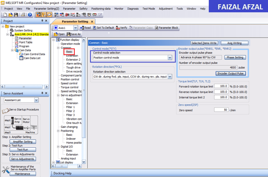
Step 4: Select Control Mode
- Action: Choose “Position Control Mode” from the available control modes.
- Purpose: Position control mode is typically used for applications requiring precise control over servo movements, based on high-speed pulse inputs from a PLC.
Step 5: Configure Position Control
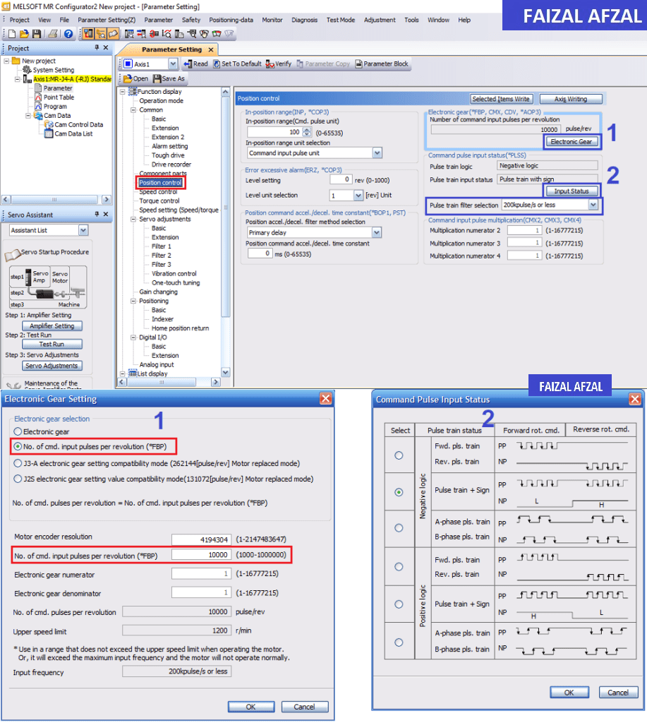
- Electronic Gear Setting:
- Action: Define the number of pulses per revolution (P/R).
- Purpose: This setting determines how many pulses are needed to complete one full revolution of the servo motor.
- Examples:
- Actuator with 10mm Pitch: Set 10,000 pulses/revolution.
- PLC Pulse Calculation: 1 pulse = 1 µm; 1000 pulses = 1 mm.
- Actuator with 6mm Pitch: Set 6,000 pulses/revolution.
- PLC Pulse Calculation: 1 pulse = 1 µm; 1000 pulses = 1 mm.
- Actuator with 10mm Pitch: Set 10,000 pulses/revolution.
- Input Status Setting:
- Action: Configure the pulse reception type.
- Purpose: Ensure compatibility with the PLC’s pulse output.
- Recommendation: For basic applications, select “Negative Logic: Pulse Train + Sign” and set the pulse train filter to “200k pulses/s or less” to avoid disturbances and ensure stable operation.
4. Wiring Diagrams and PLC Integration
To connect the MR-J4-A servo drive to various PLCs, refer to the following wiring diagrams and control tutorials:
1. Mitsubishi PLCs:
- FX3U:
- Wiring Diagram: FX3U & MR-J4-A Wiring Diagram
- Tutorial: FX3U & MR-J4-A Servo Control
 FX5U:
FX5U:
- Wiring Diagram: FX5U & MR-J4-A Wiring Diagram
- Tutorial: FX5U & MR-J4-A Servo Control
 2. Omron PLCs:
- CP1H:
- Wiring Diagram: CP1H & MR-J4-A Wiring Diagram
- Tutorial: CP1H & MR-J4-A Servo Control
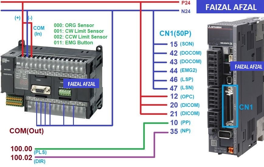 3. Keyence PLCs:
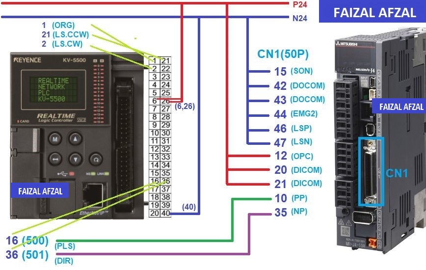
- KV-5500, KV-5000, KV-3000:
- Wiring Diagram: KV-5500 & MR-J4-A Wiring Diagram
- Tutorial: KV-5500 & MR-J4-A Servo Control
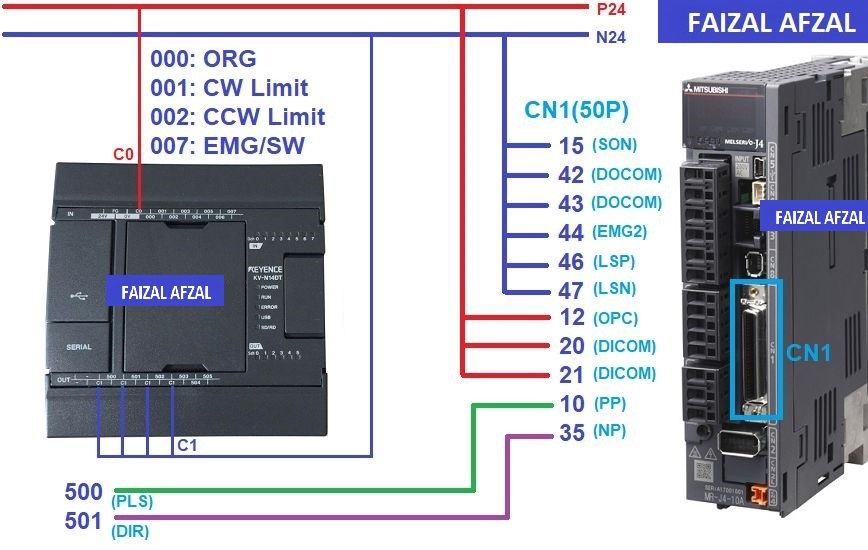
 KV-Nano:
- Wiring Diagram: KV-Nano & MR-J4-A Wiring Diagram
- Tutorial: KV-Nano & MR-J4-A Servo Control
 4. Siemens PLCs:
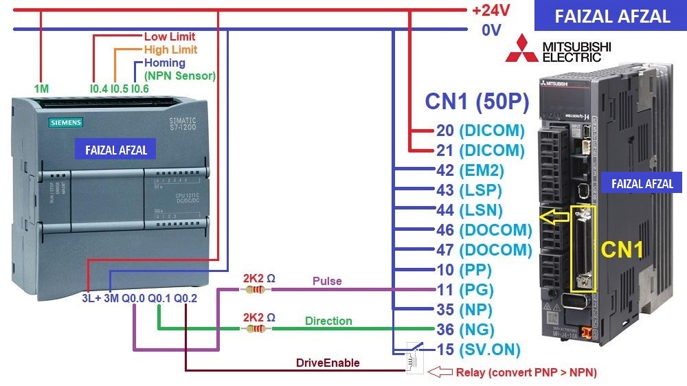
- S7-1200:
- Wiring Diagram: S7-1200 & MR-J4-A Wiring Diagram
- Tutorial: S7-1200 & MR-J4-A Servo Control
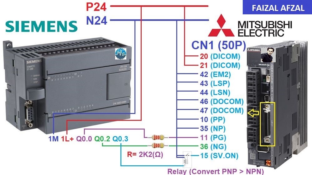
 S7-200:
- Wiring Diagram: S7-200 & MR-J4-A Wiring Diagram
- Tutorial: S7-200 & MR-J4-A Servo Control
 5. Delta PLCs:
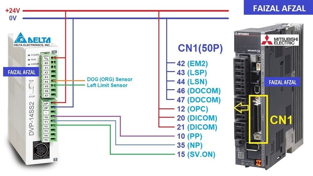
- DVP-14SS2:
- Wiring Diagram: DVP-14SS2 & MR-J4-A Wiring Diagram
- Tutorial: DVP-14SS2 & MR-J4-A Servo Control
 6. Allen-Bradley PLCs:
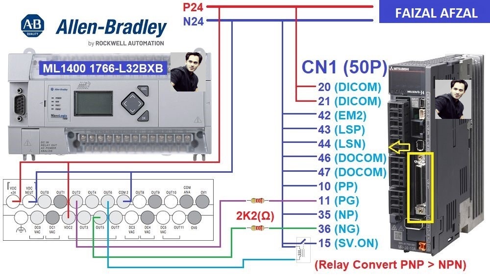
- MicroLogix 1400:
- Wiring Diagram: MicroLogix 1400 & MR-J4-A Wiring Diagram
- Tutorial: MicroLogix 1400 & MR-J4-A Servo Control
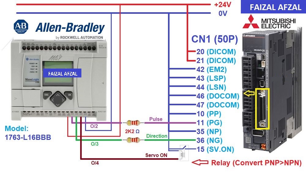
 MicroLogix 1100:
- Wiring Diagram: MicroLogix 1100 & MR-J4-A Wiring Diagram
- Tutorial: MicroLogix 1100 & MR-J4-A Servo Control
 7. Inovance PLCs:
- H3U:
- Wiring Diagram: H3U & MR-J4-A Wiring Diagram
- Tutorial: H3U & MR-J4-A Servo Control
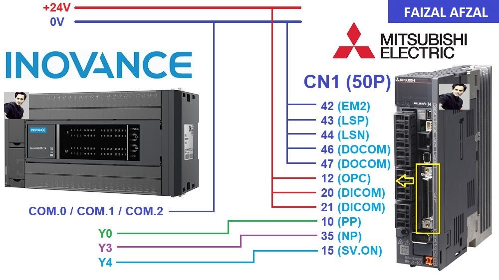
Conclusion
By following this comprehensive guide, you will be able to install, connect, and configure the Mitsubishi MR-J4-A servo drive effectively. Whether integrating with Mitsubishi, Omron, Keyence, Siemens, Delta, Allen-Bradley, or Inovance PLCs, this guide provides the necessary steps and resources to ensure a successful setup. For any further assistance, refer to the provided tutorials and wiring diagrams specific to your PLC model.
How FAIZAL Can Help?
Contact us to learn about the best implementation strategies tailored for your control system.