
THRUSTER SYSTEM
As the control system designer and developer of this project, I’ve engineered a transverse thruster system designed to enhance boat maneuverability during dynamic positioning and port maneuvers. This system effectively interprets input from one to six joysticks, translating them into proportional signals directed to the frequency inverter. Through this mechanism, the system precisely controls the speed and direction of rotation of the propellers, enabling seamless and efficient maneuvering operations.
SYSTEM OVERVIEW
The transverse thruster system enhances boat maneuverability during dynamic positioning and port maneuvers. This system retrieves set-points from one to six joysticks, producing a proportional signal to the frequency inverter. The inverter subsequently governs the speed and direction of propeller rotation, thereby activating them to facilitate precise maneuvering.

SYSTEM CONFIGURATIONS
Transverse thruster system system can have different configurations, depending on the specific clients’ requirements and needs. As an example of transverse thruster system TP 200EA is composed by the following components:
Propellers and Pod: These are the active parts of the system. they generate the transverse thrust that makes maneuvering in harbour easier by making the bow highly controllable, thus facilitating the most difficult maneuvers.
| POD | |
| Propeller configuration | Dual, counter rotating |
| Propeller diameter | 860 mm |
| Thrust | 30,9 kN (3.150 kgf) |
| Anticorrosion treatment | Epoxy paint with corrosion inhibitor |
Installation Types:
BOW (Horizontal Installation)

BOW (Vertical Installation)

Electric motor: Utilizing brushless technology, this electric motor is regulated by a variable frequency converter, enabling precise control over its speed and rotational direction.
| ELECTRIC MOTOR | |
| Type | Asynchronous tri-phases |
| Cooling | Forced air |
| Power | 195 kW |
| Weight | 1360 kg [2998 lb] (including electric motor, bell and elastic coupling) |
| Power control | Variable frequency drive (VFD) |
| Power supply (50/60 Hz) | 380 V to 480 V AC 3 phases |
| Max rotation speed | 1.200 rpm |
| Duty Cycle | S1 |
| IP rating | IP23 |
Tunnel: A hull component for the installation of the pod and propeller assembly, ensuring seamless integration and efficient propulsion within the vessel’s structure.
| TUNNEL (BOW AND STERN THRUSTER CONFIGURATION) | |||
| Hull material compatibility | Steel | Aluminum | GRP |
| Classification | RINA, Lloyd’s Register, ABS | ||
ECO (Electronic Control Unit): Contains the brain «PLC system» which reads all data and commands the electric motors.
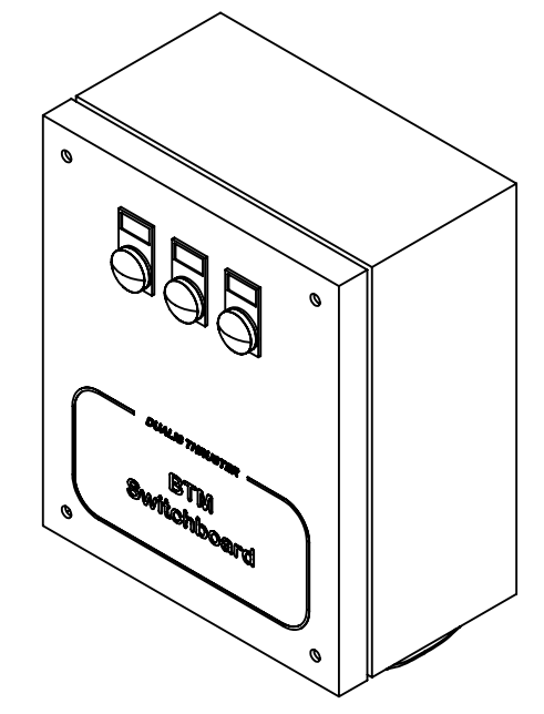
| CONTROL SWITCHBOARD | |
| Power supply | 24V DC |
| Max current consumption | 6 A |
| IP rating | IP54 |
| Installation | Vertical wall-mounted |
| Cooling | Not required |
| Connections | Dualis control panel (CANopen)VFD |
| Operating environment | Temperature: 0 – 55°C [32° – 131° F]Humidity: 5 %RH to 95 %RH (non-condensing) |
Variable Frequency Drive: Is an important electric motor speed control device for improving process control. Also reduce energy use and generate power efficiently.
| VFD | |
| Nominal Power | 195 kW |
| Power Supply | 400V 3Ph 50 or 60Hz |
| Installation | Wall-mounted |
| Cooling | Internal |
| IP rating | IP55 |
| Connections | BTM CAN |
| Operating environment | Temperature: 0 – 55°C [32° – 131° F]Humidity: 5 %RH to 95 %RH (non-condensing) |
| Optional | Harmonic Filter |
| VFD 400V 3PH 50/60Hz | |
| Weight | 122Kg |
| Max Input current | 381A |
| Max Output current | 395A |
| Power loss | 4116W |
Thruster control panel: It has a take command button to activate it in different location and send a proportional signal to the inverter, which manages the direction and speed of the propellers.

| CONTROL PANEL | |
| Power Supply | 24V DC through CANopen |
| IP rating | IP55 |
| Operating environment | Temperature: 0 – 55°C [32° – 131° F]Humidity: 5 %RH to 95 %RH (non-condensing) |
| Interface | 1x CANopen M12, Internal Buzzer |
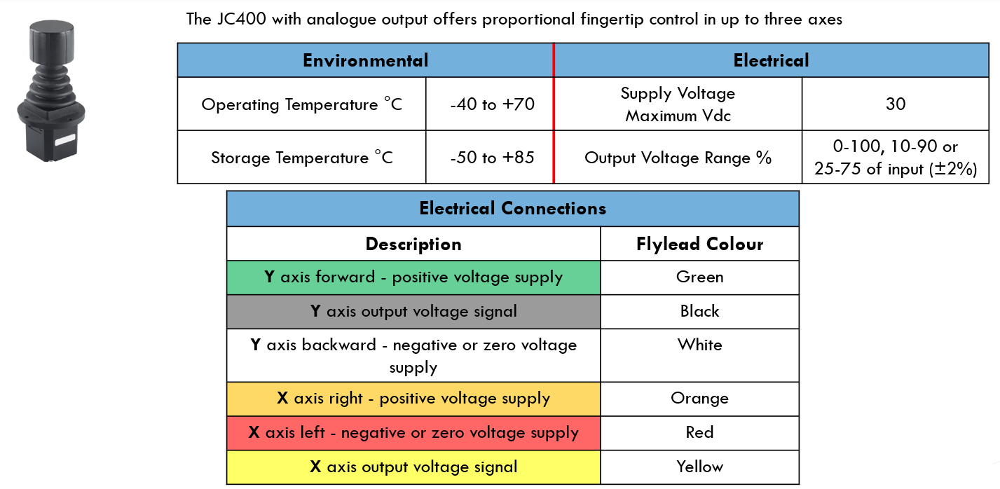
Third party control stations interface: It has a take command button to activate it in different location and send a proportional signal to the inverter, which manages the direction and speed of the propellers.

| MRS INTERFACE | |
| Power Supply | 24V DC through CANopen |
| IP rating | IP6K8 |
| Connections | Contact me for document of complete list |
| Operating environment | Temperature: -40° – 85°C [-40° – 185° F] |
| Signal required(for proportional stations) | 1 pulse take command signal1 proportional signal 0-5V for Bow Thruster1 proportional signal 0-5V for Stern Thruster |
| Signal required(for ON/OFF stations) | 1 pulse take command signal1 dry contact for PORT command1 dry contact for STBD command |
| Protocol | CAN Interface 2.0 A/B ISO11898-2, SAE J1939 |
| Item | CanOpen Y cable with M12 connectors for CANBUS connection4x2x0.5 cable for the connection of third part control signal |
SYSTEM LAYOUT

OPERATING MODES
THRUSTER CONTROL PANEL
- For single thruster, the CANopen panel has 2 electro-mechanics buttons with LED and 1 low profile proportional joystick.
- For double thruster, the CANopen panel has 2 electro-mechanics buttons with LED and 2 low profile proportional joysticks.
- The system can have up to 6 thruster control panels. It is not possible to have more than one control panel in command at any one time. The command can be transferred to any of the control panels.

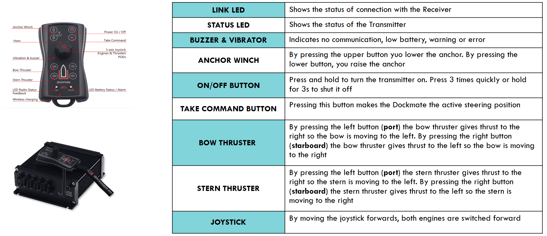
FUNCTIONS & COMMANDS
|
|
Take command button, White = OFF, Blue = ON. Press the TAKE COMMAND button of a control station to have the command on that control station. If a different control station was active, it is switched OFF and replaced by the new one. Press again the TAKE COMMAND button on the same panel for turning off the control station at the end of the use of the thruster. When the Power Management System input is used, the Blue LED is blinking up to the consent for the use of the electric power for the thruster. |
|
|
Acknowledge Alarm button, stops the buzzer. The led is red until the alarm is |
|
PROPORTIONAL |
Move the joystick on the active control station to have desired direction and |


AUTO-RELEASE
- As a safety feature, if the joystick of the station in command is not used for 15 minutes, the control station is automatically released.
- After 15 minutes without any command (nor button, nor joystick deflection), the panel buzzer will beep four times and the alarm led will blimp four times together, then the panel is automatically released.
- To prevent the automatic release, it is sufficient to move the joystick.
- After the auto-release, any panel can request command with Take command button
ALARMS
Below are some possible causes for an alarm (for more information, contact me for “Troubleshooting” documentation):
- No power to the inverter: breaker off or cable not connected. Check the indicator light “INVERTER ON” on the Electronic Switchboard.
- No communication between inverter and PLC: check the communication cables. Switch off and then on again the power to try and reset the error.
- Inverter overloaded. Try to switch OFF and then ON the power supply to the inverter. If the alarm occurs again, it could be caused by some fouling or blockage of the propellers. Make a note of the alarm code on the inverter display and communicate this to Service.
MOTOR BRAKE (OPTIONAL)
When the -optional- motor brake option is supplied, the electrical motor is fitted with an electromagnetic parking brake. The brake is used only as a parking brake, to prevent motor rotation underway; it is not used to stop (or to slow) the motor during operation:
- Motor brake (optional) is disengaged when any of the control station is in command.
- Motor brake (optional) is engaged when no station is in command.
THRUSTER STATIONS MANAGEMENT
The Default stations panel has higher priority than an external station (except Dock-mate station).
- If the Default station panel has the take control, the user can’t press the take control button of an external station
- If an external station has the take control, the user can press the take control button of Default station panel.
Communication Method:
- CAN Open communication between PLC and Joystick
- MODBUS communication between PLC and Inverter
Configuration Layout:
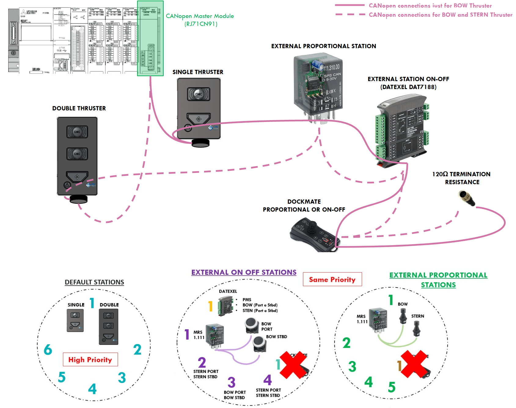
THRUSTER POWER MANAGEMENT SYSTEM (PMS)
- The DAT 7188 device allows to acquire up to 8 digital inputs and drive up to 8 PNP type transistor outputs
- Data are transmitted via CANopen protocol
- In our setup, the DAT 7188 device is known as Node 18
- The DAT 7188 is used both for the management of an external on/off thruster station (Bow and Stern) and for the Power Management System (PMS)

EXTERNAL STATION: MRS DEVICE

EXTERNAL STATION: MRS DEVICE (EXAMPLE WITH PROPORTIONAL JOYSTICK)

EXTERNAL STATION: MRS DEVICE (EXAMPLE WITH ON-OFF JOYSTICK: ELECTRICAL CONNECTIONS)

EXTERNAL STATION: MRS DEVICE (DOCKMATE)
CAN OPEN TROUBLESHOOTING:
- Master Module connection with PLC : Yellow: CAN High and Green: CAN Low
- From Master side, between CAN High and CAN Low add a 120Ω resistor
- Add a 120 Ω termination resistor at the last node of the network
- The voltage values between CAN High and CAN Low should be near to zero
- The voltage values between CAN High and Ground (0Vdc) should be greater than 2Vdc
- The voltage values between CAN Low and Ground (0Vdc) should be greater than 2Vdc
Note: the voltage values between CAN High and Groud should be greater than the voltage values between CAN Low and Ground
IMPORTANT NOTES:
- Make sure each node has a different ID
- Remember that the Baud Rate is equal to 250Kbps
- With 250Kps, the maximum length for the connection of all nodes of the network is [200/250]m
- The use of voltage stabilizer helps the integrity of CAN Open systems
- The CAN Open Nodes are very susceptible to the power supply noise
THRUSTER ALARMS : (DEFAULT STATIONS and EXTERNAL STATIONS)
A System Alarm is a general malfunction due to Inverter Fault, Supply Fault and Communication Timeout. When this alarm occurs, there is a fixed red led status on all user control stations.
The CanOpen Alarm means the lack both of CanOpen nodes (10, 11, 12, 13, 14, 15) and external stations.
- When this alarm occurs, there is a blink (1s) of led alarm
- To turn off the alarm, the user could press the ACK/ALARM button.
- Retentive counter that increments the times when any station occurs a CanOpen Alarm. This counter is used to trace faults.
The PLC autonomously manages the auto-reset of CAN Open nodes, that user has selected in the CAN Open page on the touch screen HMI.
THRUSTER ALARMS : (DEFAULT STATIONS and EXTERNAL STATIONS)
HARMONIC FILTERS: INTRODUCTION
The harmonic filter is used to improve the quality of the electrical grid by reducing the harmonic disturbances generated by generators and electronic devices connected to the grid. Variable frequency drives (VFD) on the grid can generate harmonic currents from the inverter output. These harmonics can have adverse effects on the grid in terms of efficiency losses, heating and interference.
The Thruster operates with a proportional control configuration, utilizing a VFD that may generate harmonics. To limit the distortion factor to acceptable levels, the adoption of a passive harmonic filter to reduce the negative effects of the harmonics on the electrical grid is recommended .
Passive harmonic filters, when used at rated load, can reduce Total Harmonic Distortion Current (THDi) to under 10%.
CONNECTION LAYOUT WITH HARMONIC FILTER:

TOTAL HARMONIC DISTORTION (THD):
Operating Principle The VLT® Advanced Harmonic Filter AHF 005/AHF 010 consists of a main inductor L0 and a 2-stage absorption circuit with the inductors L1 and L2, and the capacitors C1 and C2. The absorption circuit is specially tuned to eliminate harmonics starting with the 5th harmonic and is specific for the designed supply frequency. Therefore, the circuit for 50 Hz has different parameters than the circuit for 60 Hz.

The reduction of the low harmonic current emission to the rated THDi implies that the THDv of the non influenced mains voltage is lower than 2%, and the ratio of short circuit power to installed load (RSCE) is above 66. Under these conditions, the THDi of the mains current of the frequency converter is reduced to 10% or 5% (typical values at nominal load). If these conditions are not or only partially fulfilled, a significant reduction of the harmonic components can still be achieved, but the rated THDi values may not be observed.